VGA video interface
Introduction on the VGA interface
Although strict VGA monitors and graphic cards haven’t been sold for more than ten years, VGA, short for Video Graphics Array remains the best known standard for graphics on IBM PC compatible computers. There are two reasons for this. First of all, the basic VGA display modes of 80×25 character mode and 640×480 in graphics mode are supported by all modern graphic cards, independent of the extended modes supported by these cards. Therefore all computers start in one of these basic VGA modes and only after the operating system has loaded the device specific graphic card drivers the operating system will switch to a higher resolution mode. Second, despite the higher resolution and color depth, the connector used on most computers to connect the monitor with the computer is still the same as defined by the VGA standard. Therefore most people will talk about a VGA display and controller, even if it is a XGA, super VGA or whatever higher resolution version available nowadays.
Before VGA was introduced in 1987, several different display adapters were used in IBM compatible PCs. The MDA monochrome display adapter was designed for text mode, but manufacturer Hercules soon introduced an MDA compatible monochrome clone card capable of displaying graphics. Pure graphics could be viewed with a CGA color graphics adapter. This adapter was nice for playing games, but general computer use like word processing was difficult because of the low text resolution with only forty characters per line. The EGA enhanced graphics adapter tried to combine both text modes and higher resolution graphic modes, but the 640×350 graphics mode suffered from the problem that the pixels were not square when a display with a width:height ratio of 4:3 was used. VGA was introduced by IBM to solve all those problems in one new graphics definition.
Other than with MDA, CGA and EGA, the A in VGA is not used for the word adapter, but for array. This is because IBM wanted to define a video standard that would not only could be implemented as a separate video card in an extension slot, but also as an on-board chip on the motherboard. In fact the first PS/2 series were shipped with an on-board VGA chip.
Current use of the VGA connector
Although modern display interface definitions like DVI are slowly replacing the VGA interface, most lower resolution and low-cost graphic card and display implementations still use the 15 pins DB15 VGA interface as connection between the video graphics controller and monitor. The size of the connector equals the size of the DB9 serial interface connector. The DB15 VGA connector contains however 15 pins in three rows of 5 pins each. These five pins not only carry the color and synchronization signals, but also a digital I²C interface for two-way communication between the video controller and monitor. This I²C interface makes the VGA interface very versatile. The I²C interface wasn’t available on the original VGA connector definition, but has been added by the VESA DDC2 definition. Via this I2C interface the video controller and monitor can exchange information about maximum capabilities like resolution and frequencies supported which prevents incompatible display modes to be selected.
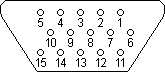
VGA DB15 connector pinout
The pin layout of the VGA interface connector is shown in the figure below. Three pins are used to carry the three basic RGB color signals red, green and blue and two pins carry the horizontal and vertical sync signal. The red, green and blue signal lines have their own ground return line. The picture shows the VGA DDC2 connector including the I²C SLC clock and SDA data lines for exchanging digital data between the video controller and the display.
| Pin | Name | Function |
|---|---|---|
| 1 | RED | Red video |
| 2 | GREEN | Green video |
| 3 | BLUE | Blue video |
| 4 | n/c | not connected |
| 5 | GND | Signal ground |
| 6 | RED_RTN | Red ground |
| 7 | GREEN_RTN | Green ground |
| 8 | BLUE_RTN | Blue ground |
| 9 | VDC | 5 VDC supply (fused) |
| 10 | GND | Signal ground |
| 11 | n/c | not connected |
| 12 | SDA | DDC / I²C data |
| 13 | HSYNC | Horizontal sync |
| 14 | VSYNC | Vertical sync |
| 15 | SCL | DDC / I²C clock |
|
Nothing ever gets built on schedule or within budget.
CHEOP'S LAW
|