Time synchronization with a Garmin GPS
- Introduction to GPS
- Computer time synchronization
- Selecting the right GPS receiver
- Mounting connectors to the Garmin 18x LVC
- Using the Garmin GPS for time synchronization
- GPS time synchronization in practice
Introduction to GPS
GPS or Global Positioning System is a navigation aid system which uses signals from satellites to calculate the actual position of a GPS capable receiver. The GPS satellites are part of the military navigation system of the US Army, but they also transmit navigation signals on public frequencies which are free to use by everyone.
The GPS system allows a maximum of 32 satellites around the earth which each transmit their own position and time on a regular interval to the earth. A GPS receiver will receive these signals and use geometric calculations to estimate the location of the receiver relative to those satellites. This GPS signal can not only be used to calculate a position, but it can also be used as a very accurate time base. To calculate a position within meters, the time signal must be accurate within nanoseconds. This, together with the broad availability of cheap GPS devices, makes the GPS system the ideal way for accurate time synchronization of computers.
Computer time synchronization
I have been operating a number of NTP time servers for some years now on different continents on this globe. NTP time servers use the Network Time Protocol to synchronize time and act as a time base for other computers in the network. On NTP capable computers, a small program is running in the background which periodically checks the time on neighboring computers and adjusts the local time according to those values. Until now I used other computers on the internet as time base for my servers, but recently I decided to setup my own accurate time source, based on a readily available GPS device. In general, the larger the number of hops between a computer and the original time source, the larger the error in synchronization will be. The number of hops between a time server and an accurate time source is normally called the stratum of that server. My time servers were all operating as stratum 2 servers which indicates that they are the second computer in row connected to the time source. Practice has shown over the last years that this gives a time accuracy of about 5 msec. A stratum 1 server can however easily reach an accuracy within a number of microseconds because the error caused by delays in the computer network is eliminated. Although for most of my work such an accuracy increase of the time base on my network is not necessary yet, promoting one of my servers to stratum 1 is a good exercise in interfacing GPS devices to computers.
Selecting the right GPS receiver
There are many cheap GPS receivers available in the market. Most of them use either an RS232, or USB connection to send their information to the attached computer. Although the clock inside the receiver itself runs with an accuracy of some nanoseconds, the transfer of the data to the computer causes such a large delay, that in practice it is not possible to synchronize the clock of the local computer with that signal with an accuracy of better than a handful of milliseconds. That kind of accuracy can also be obtained by connecting to a freely available NTP time server over the internet. Only GPS devices which have a special fast and accurate synchronization method with the computer can be used as a time synchronization device. The most expensive and accurate way to do this is to use a GPS receiver which fits in a local PCI or PCIex slot of the computer. But these cards are very expensive and not widely available. The other solution is to use the slow and inaccurate RS232 or USB interface to send general data and do the time synchronization with a pulse. The rising or falling edge of that pulse can then be used for the synchronization of the time inside the computer.
In practice, the USB interface has no mechanism to transfer a pulse signal to a host computer, but the old RS232 can process pulses with the handshake inputs present on most RS232 ports. The handshake inputs are via the UART connected with an interrupt in the computer and a change of the input state therefore causes a software action in the computer within a determined amount of time. Of course the physical properties of the port electronics, the CPU speed and machine load will have some influence on the performance, but in general you can say that this type of synchronization is magnitudes more accurate than using a serial data stream. Often an accuracy within microseconds are possible with accepting pulses through the serial interrupt system. On most GPS devices with pulse capability, the pulse is sent once every second, starting at the beginning of every new second. This is why these GPS devices are often referred to as GPS with PPS, for pulse per second.
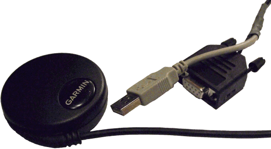
Unfortunately there are not a large number of GPS receivers which have the extra PPS output. I am using Garmin GPS receivers in Kazakhstan for my tourism activities and I have therefore first looked at the available devices from this manufacturer. Currently there are two Garmin GPS receivers which may be used with a direct connection with a computer: the Garmin GPS 16x LVS and the Garmin GPS 18x LVC. They both work on a supply voltage of +5 Volt which is directly available from a computer, they both send the general data in NMEA protocol over an RS232 interface and they both have a PPS output. Both the 16x and 18x GPS receivers are high sensitivity versions of older Garmin models. The Garmin GPS 16x LVS is more robust and especially useful on moving equipment in harsh environments. The 18x GPS receiver is also water-resistant at level IP67 and can therefore be used outdoors. The construction is less rugged, but for a static situation to synchronize a computer clock, that is not a real disadvantage. Given its lower price I have chosen for the Garmin GPS 18x LVC as the time base for my stratum 1 time server.
Mounting connectors to the Garmin 18x LVC
The Garmin 18x LVC GPS is an OEM device. It is normally used to be integrated in systems and it is either shipped with a small white print connector, or without connectors. The one I received had the white connector which I first cut off. Seven wires and shielding are available which must be connected with the RS232 connector and the power supply. This GPS model works on +5 Volt with a maximum current of 90 mA. A USB port can deliver at least 100 mA per port and that is why I have chosen to use one of the USB ports on my computer as the power source. Because on most computers the RS232 and USB ports are nearby, only short cables are necessary from the end of the GPS cable to both connectors. I used a USB connector with a small piece of cable still attached to it from a USB device which I wasn’t using anymore. But you can also buy a USB cable and use the flat A connector with a small part of the molded cable. It is probably cheaper than trying to find a separate USB connector at an electronics store.
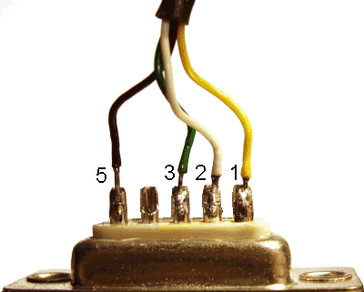
| Wire | DB9 female serial | USB | Function |
|---|---|---|---|
| Red | – | Red | +5 Volt power |
| Black (thick) | – | Black | Power ground |
| Black (thin) | 5 | – | Signal ground |
| Black (loose in cable) | – | – | not used |
| Yellow | 1 | – | PPS pulse |
| White | 2 | – | TxD from GPS |
| Green | 3 | – | RxD to GPS |
| Shield | – | Shield | Shield |
You will find a total of three black wires when examining the cable of the GPS. The thick one is used for power ground. The thin one which is on the white connector is used as signal ground. Although Garmin connects this wire in their schematics to the power supply ground near the supply, this is incorrect from a signal quality point of view. Both black wires are already connected in the GPS device and by connecting them again near the power supply, the thin wire will also carry some of the supply current causing the ground level in that wire to go up and down depending of the current drawn by the GPS. This is undesirable and may cause problems in the communication. The third black wire can be found inside the cable. It isn’t connected and shouldn’t be connected in our application.
Shielding is merely to stop outside interference to distort the communication. With short cable lengths like the 5 meter which is normally supplied with the Garmin GPS 18x LVC, the low baud-rate which can not exceed 19200 bps and the environment where the GPS receiver is used (you probably don’t have any heavy motors or welding equipment installed near the computer you want to synchronize) it is not necessary to shield the last small part from the GPS cable to the RS232 port. It is therefore sufficient that you connect the shielding to the shielding of the USB cable. If you connect everything according to the table above, the result will be as below.
Using the Garmin GPS for time synchronization
From this point on, I assume that you are running some sort of Unix based system. This may be Linux, FreeBSD or some commercial variant like HP-UX. Unfortunately I have found that synchronizing a Windows computer with a GPS with PPS signal doesn’t work well. Even with specialized software which claims to handle the PPS pulse and the NMEA output of the receiver correctly I have seen errors of several seconds on my own computers.
I assume that you will use the Garmin 18x LVC GPS without reprogramming. It works out of the box for time synchronization, so reprogramming is not really necessary. I reprogrammed it to let it communicate at a higher baud rate of 19200 bps, compared to the default 4800 bps and to output some more NMEA sentences with position data. But that is just for fun and for some future projects I have in mind with interfacing GPS devices to computers. The Garmin 18x LVC will work out of the box in the configuration I describe below.
Install ntpd
Ntpd is the daemon which helps you to keep your internal computer clock synchronized with a time source. The ntpd daemon understands the Network Time Protocol and can work both as a client and server in an NTP network. Besides that it can synchronize with local time sources. The ntpd daemon cannot interface with GPS devices directly, but it has defined a number of interfaces which can be used by other daemons to interface GPS time with ntpd.
The ntpd daemon is either already installed on your system, or it can be downloaded from one of the package repositories. Linux distributions like Debian, Ubuntu and RedHat all have ntpd in their standard repository. If for your system no readily available ntpd package is available, you can download it from the project site www.ntp.org. Installation should be straight forward.
Install gpsd
Because ntpd can’t communicate directly with a GPS device, a separate daemon is needed for the GPS communication. As always in Unix land, there is more than one solution to this problem, but I have used the gpsd daemon for this task. The gpsd daemon is the most versatile of all GPS daemons currently available. It does not only interface well with most GPS models available, but it also communicates nicely with ntpd and has a special interface to make it possible to easily integrate in web pages etc. The gpsd daemon can be downloaded from www.berlios.de/software/gpsd/. It is available in source code, not in a pre-compiled package, so you have to build it yourself.
In the default configuration, the gpsd daemon is installed in the /usr/local/sbin directory. I didn’t change the compilation settings to make it easy in the future to download and install a new version of the software. Instead, I linked to this daemon from the general /usr/sbin directory with the command
ln -s /usr/local/sbin/gpsd /usr/sbin/gpsdwhich makes the gpsd daemon available, even if /usr/local/sbin is not in your PATH.
The gpsd daemon is normally not shipped with a script which starts it when the computer is booted. I therefore wrote my own. It is Centos based, but you shouldn’t have much problems to adapt it to specific installation. There are two files involved. One file is added in the /etc/rc.d/init.d directory and contains the startup script. The other file goes in the /etc/sysconfig directory and contains the settings for startup.
/etc/sysconfig/gpsd
DAEMON_OPTS="-n"
BAUDRATE="4800"
DEVICE="/dev/ttyS0"
You should change the BAUDRATE and DEVICE settings in this file according to your specific situation. An out of the box GPS communicates at 4800 baud. The device /dev/ttyS0 is the fist serial device on the computer, also often referred to as COM1.
/etc/rc.d/init.d/gpsd
#!/bin/bash
#
# gpsd          This shell script takes care of starting and stopping
#               gpsd (GPS daemon).
#
# chkconfig: 2345 50 80
# description: gpsd is the GPS daemon. \
# The GPS daemon gets the actual position and time information from \
# an attached GPS device and makes this information available for \
# other daemons and applications.

# Source function library.
. /etc/init.d/functions

# Source networking configuration.
. /etc/sysconfig/network

if [ -f /etc/sysconfig/gpsd ];then
        . /etc/sysconfig/gpsd
fi


RETVAL=0
prog="gpsd"

start() {

        setserial $DEVICE low_latency
        stty $BAUDRATE -F $DEVICE

        echo -n $"Starting $prog: "
        daemon gpsd $DAEMON_OPTS $DEVICE
        RETVAL=$?
        echo
        [ $RETVAL -eq 0 ] && touch /var/lock/subsys/gpsd
        return $RETVAL
}

stop() {
        echo -n $"Shutting down $prog: "
        killproc gpsd
        RETVAL=$?
        echo
        [ $RETVAL -eq 0 ] && rm -f /var/lock/subsys/gpsd
        return $RETVAL
}

# See how we were called.
case "$1" in
  start)
        start
        ;;
  stop)
        stop
        ;;
  status)
        status gpsd
        RETVAL=$?
        ;;
  restart|reload)
        stop
        start
        RETVAL=$?
        ;;
  condrestart)
        if [ -f /var/lock/subsys/gpsd ]; then
            stop
            start
            RETVAL=$?
        fi
        ;;
  *)
        echo $"Usage: $0 {start|stop|restart|condrestart|status}"
        RETVAL=3
esac

exit $RETVAL
Connect gpsd and ntpd
I assume that you have tested gpsd according to the installation instructions which come with the daemon source. If it isn’t working you should try to solve that problem first. The best way to test the gpsd daemon is to start it in the foreground. This starts the gpsd daemon in debug mode and outputs all information directly to the screen. You should see output similar to
$ sudo /usr/local/sbin/gpsd -n -N -D2 /dev/ttyS0
gpsd: launching (Version 2.91dev)
gpsd: listening on port gpsd
gpsd: running with effective group ID 0
gpsd: running with effective user ID 0
gpsd: opening GPS data source at '/dev/ttyS0'
gpsd: speed 19200, 8N1
gpsd: garmin_gps Linux USB module not active.
gpsd: speed 9600, 8O1
gpsd: speed 19200, 8N1
gpsd: gpsd_activate(): opened GPS (fd 4)
gpsd: NTPD ntpd_link_activate: 0
gpsd: => Probing device subtype 0
gpsd: => Probing device subtype 1
gpsd: => Probing device subtype 2
gpsd: => Probing device subtype 3
gpsd: => Probing device subtype 4
gpsd: => Probing device subtype 5
gpsd: => Probing device subtype 6
gpsd: => Probing device subtype 7
gpsd: => Probing device subtype 8
gpsd: PPS cycle: 584180992, duration: 584180992 @ 1263141876.000000
gpsd: PPS pulse rejected
gpsd: PPS cycle: 584280994, duration: 100002 @ 1263141876.100002
gpsd: PPS pulse rejected
gpsd: PPS cycle: 1000000, duration: 899998 @ 1263141877.000000
gpsd: PPS cycle: 999999, duration: 100001 @ 1263141877.100001
gpsd: PPS pulse rejected
gpsd: PPS cycle: 999998, duration: 899997 @ 1263141877.999998
gpsd: PPS cycle: 1000000, duration: 100003 @ 1263141878.100001
gpsd: PPS pulse rejected
The first lines show the result of the auto-probing routines of the gpsd daemon. The program checks different baud rates and data formats to determine the GPS model attached to the serial port. After a few seconds we see PPS pulses coming in. The first pulses are rejected because cycle time and duration is not within the bounds gpsd expects them to be. But this problem should be over after a few pulses have been detected.
You will probably see the message PPS pulse rejected every third line or so. This is not an error but caused by the way gpsd works. Some GPS devices may emit a positive pulse and others a negative. Furthermore the RS232 circuitry negates the pulse value due to its design. Therefore gpsd detects both the rising and falling edge of the pulse and after comparison with the computer time decides which one to skip. Therefore every one of two pulse edges is rejected per second.
If your output looks like this output, you can stop gpsd with Ctrl-C and prepare the ntpd daemon to receive synchronization information from gpsd. The configuration file is called /etc/ntp.conf on most systems. A basic configuration should look like
# Permit time synchronization with our time source, but do not
# permit the source to query or modify the service on this system.

restrict default kod nomodify notrap nopeer
restrict -6 default kod nomodify notrap nopeer

# Permit all access over the loopback interface.  This could
# be tightened as well, but to do so would effect some of
# the administrative functions.
restrict 127.0.0.1
restrict -6 ::1

# Read the rough GPS time from device 127.127.28.0
# Read the accurate PPS time from device 127.127.28.1

server 127.127.28.0 minpoll 4 maxpoll 4
fudge 127.127.28.0 time1 0.535 refid GPS
server 127.127.28.1 minpoll 4 maxpoll 4 prefer
fudge 127.127.28.1 refid PPS

# Use servers from the ntp pool for the first synchronization,
# or as a backup if the GPS is disconnected

server 0.pool.ntp.org
server 1.pool.ntp.org
server 2.pool.ntp.org
server 3.pool.ntp.org

# Drift file.  Put this in a directory which the daemon can write to.
# No symbolic links allowed, either, since the daemon updates the file
# by creating a temporary in the same directory and then rename()'ing
# it to the file.
driftfile /var/lib/ntp/drift

statsdir /var/log/ntp/

statistics loopstats peerstats clockstats
filegen loopstats file loopstats type day enable
filegen peerstats file peerstats type day enable
filegen clockstats file clockstats type day enable

# Key file containing the keys and key identifiers used when operating
# with symmetric key cryptography.
keys /etc/ntp/keys
In this configuration we have four normal NTP servers taken from the NTP pool to bring the clock within a number if milliseconds of the real time. This also serves as a backup system, if any problems arise with the GPS clock.
The serial acquired GPS time is provided via interface 127.127.28.0. This time is absolute and available directly after the GPS device is connected with the computer, but due to the serial transfer mechanism to get the info to the computer, it may fluctuate with 50 msec or more. The value 0.535 is a correction parameter which must be fine tuned by hand. On my system this gives an approximately correct time generated by the GPS device when it outputs all available NMEA sentences over 19200 bps. In your specific situation you may have to increase or decrease this value.
Once the PPS synchronization is established by gpsd, the accurate time according to this signal is interfaced with ntpd via the 127.127.28.1 interface. This will however only be the case when the computer clock has reached the correct time within a window of about 100 msec. The ntpd daemon will then switch over to the PPS clock signal.
Testing the configuration
You can test the configuration with the following two commands
/etc/init.d/gpsd start
/etc/init.d/ntpd start
This will start both daemons. If you receive OK messages for both start commands, you can check the time synchronization with
ntpq -p
This will output a list of time sources ntpd is synchronizing with. The first two lines starting with SHM are the most important because these are the GPS and PPS clock references. After some time (this may take minutes to hours depending on the initial setting of your computer clock), these lines should look like below. Values may differ in your situation.
$ ntpq -p
     remote           refid      st t when poll reach   delay   offset  jitter
==============================================================================
+SHM(0)          .GPS.            0 l    6   16  377    0.000   28.775  10.971
*SHM(1)          .PPS.            0 l    5   16  377    0.000   -0.001   0.002
The first line indicates that the GPS clock has an offset of 28.775 msec with a variation of 10.971 msec. This is the time obtained from the GPS time which is transmitted over the serial interface. The second line tells us that the computer time is now locked at -1 microsecond from the PPS time source with a variation of 2 microseconds.
Starting the daemons at boot time
You have to make sure that both daemon are started at every reboot. On the RedHat family of Linux distributions you can use the command chkconfig for this task. Both daemons can marked for starting at every reboot with the commands
chkconfig --add ntpd
chkconfig --add gpsd
This causes the daemons to start at every reboot. On other Unix flavors similar commands exist.
GPS time synchronization in practice
Currently my public time server ntp4.linocomm.net is running with this synchronization. The actual synchronization downloaded with the ntpq -p command is shown below. This list is refreshed every five minutes. You will see that the clock is running with only a few microseconds difference from the .PPS. clock signal which is running on the SHM(1) device.
|
If you miss one issue of any magazine,
it will be the issue which contained the article,
story or installment you were most anxious to read.
JOHNSON'S THIRD LAW
|