RS232 serial null modem cable wiring
- Null modem, an introduction
- Original use of RS232
- Null modem without handshaking
- Null modem with loop back handshaking
- Null modem with partial handshaking
- Null modem with full handshaking
- Null modem layout selection table
Null modem, an introduction
Serial communications with RS232. One of the oldest and most widely spread communication methods in computer world. The way this type of communication can be performed is pretty well defined in standards. I.e. with one exception. The standards show the use of DTE/DCE communication, the way a computer should communicate with a peripheral device like a modem. For your information, DTE means data terminal equipment (computers etc.) where DCE is the abbreviation of data communication equipment (modems). One of the main uses of serial communication today where no modem is involved—a serial null modem configuration with DTE/DTE communication—is not so well defined, especially when it comes to flow control. The terminology null modem for the situation where two computers communicate directly is so often used nowadays, that most people don’t realize anymore the origin of the phrase and that a null modem connection is an exception, not the rule.
In history, practical solutions were developed to let two computers talk with each other using a null modem serial communication line. In most situations, the original modem signal lines are reused to perform some sort of handshaking. Handshaking can increase the maximum allowed communication speed because it gives the computers the ability to control the flow of information. High amounts of incomming data is allowed if the computer is capable to handle it, but not if it is busy performing other tasks. If no flow control is implemented in the null modem connection, communication is only possible at speeds at which it is sure the receiving side can handle the amount information even under worst case conditions.
Original use of RS232
When we look at the connector pinout of the RS232 port, we see two pins which are certainly used for flow control. These two pins are RTS, request to send and CTS, clear to send. With DTE/DCE communication (i.e. a computer communicating with a modem device) RTS is an output on the DTE and input on the DCE. CTS is the answering signal comming from the DCE.
Before sending a character, the DTE asks permission by setting its RTS output. No information will be sent until the DCE grants permission by using the CTS line. If the DCE cannot handle new requests, the CTS signal will go low. A simple but useful mechanism allowing flow control in one direction. The assumption is, that the DTE can always handle incomming information faster than the DCE can send it. In the past, this was true. Modem speeds of 300 baud were common and 1200 baud was seen as a high speed connection.
For further control of the information flow, both devices have the ability to signal their status to the other side. For this purpose, the DTR data terminal ready and DSR data set ready signals are present. The DTE uses the DTR signal to signal that it is ready to accept information, whereas the DCE uses the DSR signal for the same purpose. Using these signals involves not a small protocol of requesting and answering as with the RTS/CTS handshaking. These signals are in one direction only.
The last flow control signal present in DTE/DCE communication is the CD carrier detect. It is not used directly for flow control, but mainly an indication of the ability of the modem device to communicate with its counter part. This signal indicates the existence of a communication link between two modem devices.
Null modem without handshaking
How to use the handshaking lines in a null modem configuration? The simplest way is to don’t use them at all. In that situation, only the data lines and signal ground are cross connected in the null modem communication cable. All other pins have no connection. An example of such a null modem cable without handshaking can be seen in the figure below.
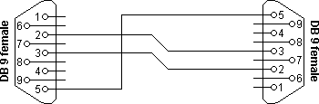
| Connector 1 | Connector 2 | Function |
|---|---|---|
| 2 | 3 | Rx ◄ Tx |
| 3 | 2 | Tx ► Rx |
| 5 | 5 | Signal ground |
Compatibility issues
If you read about null modems, this three wire null modem cable is often talked about. Yes, it is simple but can we use it in all circumstances? There is a problem, if either of the two devices checks the DSR or CD inputs. These signals normally define the ability of the other side to communicate. As they are not connected, their signal level will never go high. This might cause a problem.
The same holds for the RTS/CTS handshaking sequence. If the software on both sides is well structured, the RTS output is set high and then a waiting cycle is started until a ready signal is received on the CTS line. This causes the software to hang because no physical connection is present to either CTS line to make this possible. The only type of communication which is allowed on such a null modem line is data-only traffic on the cross connected Rx/Tx lines.
This does however not mean, that this null modem cable is useless. Communication links like present in the Norton Commander program can use this null modem cable. This null modem cable can also be used when communicating with devices which do not have modem control signals like electronic measuring equipment etc.
As you can imagine, with this simple null modem cable no hardware flow control can be implemented. The only way to perform flow control is with software flow control using the XOFF and XON characters.
Null modem with loop back handshaking
The simple null modem cable without handshaking shows incompatibilities with common software. The main problem with this cable is that there is a possibility for the software to hang if it checks the modem signal lines in a proper way. I.e. with this null modem cable, good written programs will perform worse than badly written programs.
To overcome this problem and still be able to use a cheap null modem communication cable with only three lines in it, a fake null modem cable layout has been defined. The null modem cable with loop back handshaking resulted from this.
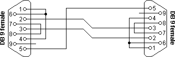
| Connector 1 | Connector 2 | Function |
|---|---|---|
| 2 | 3 | Rx ◄ Tx |
| 3 | 2 | Tx ► Rx |
| 5 | 5 | Signal ground |
| 1 + 4 + 6 | – | DTR ► CD + DSR |
| – | 1 + 4 + 6 | DTR ► CD + DSR |
| 7 + 8 | – | RTS ► CTS |
| – | 7 + 8 | RTS ► CTS |
The main purpose of this null modem cable is to let well defined software think there is handshaking available, with a null modem cable which has no provisions for it.
Compatibility issues
Consider first the DSR signal (pin 6). This input indicates that the other side is ready to start communicating. In the layout, the line is linked back to the DTR output (pin 4). This means, that the software doesn’t see the ready signal of the other device, but its own. The same holds for the CD input (pin 1). The assumption is, that if software has been written to check the DSR line to test communication availability, it will probably also set the DTR output to indicate its own state. This is true for at least 99% of all serial communication software. This implies that at least 99% of all serial communication software is capable of faking its own DSR check with this null modem cable.
The same trick is used with the CTS input. In the original use, RTS is set, and then CTS is checked before starting the communication. By setting the RTS output (pin 7) the CTS input on the same connector (pin 8) is receiving clearance immediately. There is no possibility of a software hangup because of dangling RTS requests.
Other issues to consider
The null modem cable with loop back handshaking is often advised as the best low cost available null modem cable. But, is it really so good? The simple null modem cable without handshaking has the disadvantage that it does not permit proper written software to communicate with it. Software which is aware of the lack of handshaking signals can however use it without problems.
The null modem cable with loop back handshaking can be used with more software, but it has no functional enhancements over the simple cable! There is no way both devices can control data flow, other than by using XON/XOFF handshaking. If the software is designed for using hardware flow control it seems to work with this null modem cable, but on unpredictable moments, data loss may occur. This means that the null modem cable allows communication as long as no flow control is needed, but when data speeds reach the limit the receivers can handle, communication may stop immediately without an assignable reason. Therefore, although this null modem cable is cheap and easy to make, use it with care! Despite these warnings, this type of null modem cable has been used successfully between Windows 95/98/ME computers with a Direct Cable Connection.
Null modem with partial handshaking
The simple null modem cable and the null modem cable with loop back handshaking are useful, but have no provisions for hardware flow control. If it is absolutely necessary that hardware flow control is used, the null modem with partial handshaking can be an alternative.
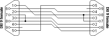
| Connector 1 | Connector 2 | Function |
|---|---|---|
| 1 | 7 + 8 | CTS2 + CD1 ◄ RTS2 |
| 2 | 3 | Rx1 ◄ Tx2 |
| 3 | 2 | Tx1 ► Rx2 |
| 4 | 6 | DTR1 ► DSR2 |
| 5 | 5 | Signal ground |
| 6 | 4 | DSR1 ◄ DTR2 |
| 7 + 8 | 1 | RTS1 ► CTS1 + CD2 |
Compatibility issues
This null modem cable is the best of two worlds. There is the possibility of hardware flow control without being incompatible with the original way flow control was used with DTE/DCE communication. Let us first consider the RTS/CTS flow control lines present on pins 7 and 8. As with the loop back null modem cable, these signals are not connected to the other device, but directly looped back on the same connector. This means, that RTS/CTS flow control is allowed to be used in the software, but it has no functional meaning. Only when the software at the other side checks the CD signal at pin 1, the RTS information will reach the other device. This would however be only the case in specifically developed software which uses the CD input for this purpose.
More important however is the cross connection of the DSR (pin 6) and DTR (pin 4) lines. By cross connecting these lines, their original function is simulated pretty well. The DTR output is used to signal the other device that communication is possible. This information is read on the DSR input, the same input used for this purpose with modem communication. Because of this cross connection, the DTR output line can be used for simple flow control. Incomming data is allowed when the output is set, and blocked if the output is not set.
Software using only the RTS/CTS protocol for flow control cannot take advantage of the partial handshaking null modem cable. Most software however will also check the DSR line and in that case—when using the null modem cable with partial handshaking—the best possible hardware flow control can be achieved which is still compatible with the original use with modems.
Null modem with full handshaking
The most expensive null modem cable is the null modem cable suitable for full handshaking. In this null modem cable, seven wires are present. Only the ring indicator RI and carrier detect CD signal are not linked. The cable is shown in the following figure.
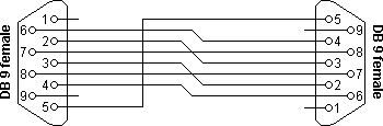
| Connector 1 | Connector 2 | Function |
|---|---|---|
| 2 | 3 | Rx ◄ Tx |
| 3 | 2 | Tx ► Rx |
| 4 | 6 | DTR ► DSR |
| 5 | 5 | Signal ground |
| 6 | 4 | DSR ◄ DTR |
| 7 | 8 | RTS ► CTS |
| 8 | 7 | CTS ◄ RTS |
Compatibility issues
The null modem cable with full handshaking does not permit the older way of flow control to take place. The main incompatibility is the cross connection of the RTS and CTS pins. Originally, these pins are used for a question/answer type of flow control. When the full handshaking null modem cable is used, there is no request anymore. The lines are purely used for telling the other side if communication is possible.
The main advantage of this cable is, that there are two signalling lines in each direction. Both the RTS and DTR outputs can be used to send flow control information to the other device. This makes it possible to achieve very high communication speeds with this type of null modem cable, provided that the software has been designed for it. Because of the high possible connection speed, this null modem cable can be used with Interlink to connect two MS-DOS PC’s.
This is the type of cable Microsoft recommends for the direct cable connection in their knowledge base article. For the DB9 connector they also added a connection of DTR to CD on each connector but they didn’t define this connection for the DB25 connector version and they also didn’t mention the CD input in the descriptive text, so it is safe to leave the CD input disconnected.
Null modem layout selection table
The right null modem cable to choose mainly depends on the application and the software that will be used. As a general guide line, I would advise the following.
| Cable without handshaking | Loop back handshaking | Partial handshaking | Full handshaking | |
|---|---|---|---|---|
| Software flow control only | +++ | ++ | + | + |
| DTE/DCE compatible hardware flow control at low speeds | – | +++ | ++ | – |
| DTE/DCE compatible flow control at high speeds | – | + | +++ | – |
| High speed communication using special software | – | – | ++ | +++ |
Choose your null modem cable
The null modem cable with partial handshaking works in most cases. If you are developing software which must work with all kinds of cables, it is best to use software flow control only and ignore all modem control inputs.
|
Before God we are all equally wise;
and equally foolish. ALBERT EINSTEIN
|