I²C interface tutorial
- History of the I²C interface
- Physical properties of the I²C interface
- Start and stop conditions on the I²C interface
- Data transfer with I²C
- Synchronization and arbitration
History of the I²C interface
In the late seventies of the previous century, small microprocessors and digital operating integrated circuits were slowly overtaking jobs in consumer products like television sets from analog circuits. Philips—one of the main manufacturers of consumer electronics—was looking for an interface that could be used to let ICs communicate with each other with a low-cost connection and at moderate speeds. The common method of inter-IC communication at that time was via a parallel 8 bit wide bus. This bus structure—which is also used to connect memory and peripherals to CPUs—requires not only eight data lines for the data transfer, but also several lines for addressing specific peripheral ICs. Philips researched for a way to reduce the necessary area on the printed circuit boards for these buses and the costs involved by reducing the number of communication lines to only two. This inter-IC bus was called IIC or I²C and became widely implemented in situations where cost and size reduction were more important than data speed.
Philips managed to reduce the number of data lines of the I²C bus by switching from parallel to synchronous serial communication. The I²C bus consists of only two lines where one called SDA is carrying the data bits and the second called SCL is used as a clock signal. The messages sent over the I²C bus contain addresses to define which device should reply to them. The I²C bus was defined in such a way that it allowed many integrated circuits of different design and model to be interconnected. Small input filters on the receiver side of the ICs were implemented to reduce noise, and provisions were made that slower ICs could postpone the communication for a short time. Although the first application of the I²C bus was in television sets to control ICs for audio an video processing, the bus is now widely used in all types of control and signal processing applications, for example in the VGA interface or HDMI interface to exchange display settings between the video controller and the attached monitor. This wide spread success is mainly because of the versatility of the bus.
- Every participant on the I²C bus has its unique address
- Communication takes place in master-slave mode, where the design allows multiple masters on one bus
- Collision detection mechanisms are present to prevent more than one device occupying the bus at any given time
- Communication between master and slave is bi-directional
- Several speeds are possible. Current implementations allow speeds of 100, 400 and 3400 kbps. These three different data speeds are called standard-mode, fast mode and high-speed mode.
Physical properties of the I²C interface
In the physical design of the I²C bus, Philips defined a data line SDA and a clock line SCL. These two lines create a synchronous serial bus. The number of devices connected to the bus is only limited by the total allowed bus capacitance of 400 pF. Because most ICs with an I²C interface use low-power, high-impedance CMOS technology, many ICs can be connected to the I²C bus before that maximum capacitance is reached. The clock signal on the bus is generated by one of the masters connected to the I²C bus. When idle, the SDA and SCL lines are pulled up to the supply voltage with a pull-up resistor.
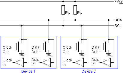
Supply voltage levels are flexible. It is possible to use a 5 VDC supply for the bus and components, but even voltages of less than 2 VDC can be used. This allows the I²C bus to be implemented in several types of circuits without the need of its own power supply. Level shifters can be used when an I²C bus contains two sub sections with different supply voltages, for example 3.3 Volt and 5 Volt. I²C inputs on fast mode and high-speed mode devices use Schmitt-trigger logic to reduce the effects of noise.
Start and stop conditions on the I²C interface
Only masters can initiate data transfer sessions on the I²C bus. When a master on the I²C bus wants to communicate with a slave, it first has to take control of the bus. This is only possible when the bus is idle, i.e. both the SDA and SCL lines are high. The master has to create a START condition to signal other devices on the I²C bus that it will take control. To create a START condition, the clock line SCL remains high, while the master changes the SDA line to the low condition. This is a unique situation. During normal data transfer, the SDA data line changes only state when the SCL clock line is low. Every device on the I²C bus knows a new communication session will start when the data line changes to low while the clock line is high. This allows for re-synchronization when errors were present during the previous data transfer and some devices lost synchronization.
The end of a communication session is signaled by a STOP condition. The STOP condition is generated by changing the SDA data line to high while the clock line SCL is high. Just as with the START condition, this SDA change cannot happen during normal data transfer and attached ICs can reset their internal communication logic when the previous transfer ended in an error. After the STOP condition is generated, the I²C bus is considered free again when a specific amount of time has elapsed. This time is dependent on the bus speed.
Repeated START conditions can happen when a START condition is generated without a STOP condition ending the previous transfer session. After a repeated START condition, the bus remains busy and it can therefore generally be considered as a normal START condition.
Data transfer with I²C
In between the START and STOP conditions, the data transfer takes place. The unity of data transfer on the I²C bus is the byte. Data is transferred from a master to a slave, or back to the master in bytes. The first byte in each data transfer is the slave address. Only seven of the eight bits in the address byte are used to define the slave address. The lowest order bit indicates a read, or write request. A low bit indicates a write, a high bit a read request. Data is transferred with the most significant bit first.
During the data transfer, the master changes the state of the clock line SCL periodically to from high to low and back. Data on the SDA line may only be changed when the SCL line is in the low state. After the SDA line has been changed to the desired bit value the SCL line is changed to high again to signal the other ICs on the I²C bus that a valid data bit is present on the line. ICs on the I²C bus often have very limited memory, logic and speed. Therefore, every sent byte has to be acknowledged by the intended receiver. After the master has sent a byte, it sends a ninth clock pulse during which the acknowledgement should take place. As told before, the SDA line is pulled up by a resistor. The slave should pull down the SDA line during the ninth clock pulse. If this doesn’t happen and instead the SDA line is in the high state, the master knows that an error happened during the data transfer.
If the slave device is busy with a task, or just very slow by design and it cannot receive another byte before the previous one is processed, the period after the ninth acknowledge bit can be used to let the master wait. Again, the logic to slow down the master is very simple. When the master wants to send the next byte, the SCL line must be taken down again by the master. The master changes the clock line SCL to the high state, by changing its output to high impedance. Normally the pull-up resistor on the bus will change the SCL line to the high state, but if the slave wants to postpone communications, it simply pulls down the SCL line for the period it needs to perform other tasks or process the previous byte. The master only continues data transfer when it senses that the SCL line has reached the high state. This creates a very simple and effective way for slow slaves with limited processing and memory capabilities to communicate with faster masters. When all bytes are received and processed, the STOP condition is generated by the master to free the bus for other communication sessions.
Special situations: synchronization and arbitration
One of the powerful properties of the I²C bus is the possibility to connect more than one master to the bus. This can be a source of problems. First of all, each master has to generate its own clock signal. Clock signal rates may vary somewhat causing synchronization problems. Furthermore a system must be implemented to prevent more than one master to be active on the bus on any given moment. Both problems are solved by the synchronization and arbitration logic in the I²C bus masters.
Every I²C master has two internal counters. One counter is used to count the length of a high value on the SCL clock line of the I²C bus, the other is used to count the length of a low value on the SCL line. If only one master is present on the bus, these two counters define the clock frequency. When two or more I²C masters are connected in parallel, it may be that these counters do not run at the same speed. This is where synchronization kicks in. As described before, the SCL clock line of the I²C bus is pulled up to the supply voltage with an external pull-up resistor. Consider the situation that the SCL line is in high state, and all internal counters of the attached masters count until the moment has reached to switch to the low state. As soon as one of the masters on the bus switches the SCL line to the low state, the other masters sense the situation and reset their counter, regardless of the current count. They all internally switch to the low state and their low-period counter starts counting.
After some time, the first of those low-period counters will reach its end and that I²C master will decide to switch the SCL line again to the high state. Because of the physical design of the bus where a pull-up resistor is used to initiate the high state, the SCL clock line will not switch to the high state as long as there is at least one I²C master still counting the low period. When the last I²C master decides to switch SCL to the high state, the clock line changes state. All the masters with faster counters were waiting for this moment and when the line switches state, they all start to count the length of the high state. With this system of synchronization, the length of the high period of the SCL clock line is defined by the fastest I²C master attached to the bus, and the length of the low period by the slowest participant.
Arbitration is another interesting case. Consider the situation where the I²C bus is idle, and two or more masters want to occupy the bus at the same time. Some procedure is necessary to decide which master is granted access, and which master should wait for the next idle time. This procedure is called arbitration.
We already know, that a master initiates a communication session with the START condition. The SDA line is pulled down while the SCL clock line remains high. If two masters do this at the same time, they cannot see if the START condition is caused by their own action, or by another master. Therefore they will continue their protocol and send the first data byte to the projected slave. When each bit is set at the SDA line, the master senses which value is present at the SDA line. A master can only pull the SDA data line to the low state, but not to high. If the master wanted to send a high bit, but it senses a low value at the SDA line after the SCL clock line changed to high, it knows that another master is also sending. The master that first detects this situation aborts the communication and will schedule for a retry later on. The other master continues communication and is granted priority on the I²C bus. It can take quite a few bits before a master senses that another master is also sending data. Especially when both masters address the same slave—which results in the same bit pattern in the address byte—it may take quite a lot of bits before one of the masters aborts the communication. This has however no negative influence on the communication of the other master because no bits will be corrupted.
A special situation occurs with ICs which act both as master and slave on the same I²C bus. When arbitrage takes place, it may be the case that the losing master is actually the slave that the winning master wants to contact. In those cases the losing master should directly switch to slave mode and interpret the previous bits to see if its slave address is selected by the other master.
|
Yes, we have to divide up our time like that,
between our politics and our equations.
But to me our equations are far more important,
for politics are only a matter of present concern.
A mathematical equation stands forever.
ALBERT EINSTEIN
|