Pulse induction metal detector with DSP
Introduction to metal detection
Most metal detectors work on the fact that metals in a magnetic field change the behavior of the field. There are two general approaches to detect these changes. In one approach, an alternating current is provided to a transmit coil. A receive coil is used to pick up the magnetic field generated by the transmitter. If a piece of metal comes inside the range of the magnetic field lines, the receive coil can detect a change in both amplitude and phase of the received signal. The amount of amplitude change and phase change is an indication for the size and distance of the metal, and can also be used to discriminate between ferrous and non-ferrous metals.
In the other approach, current pulses are sent to the transmit coil. The magnetic field caused by these pulses start eddy currents in metals close to the coil. If the magnetic field is switched of fast enough, the eddy currents can be detected with the transmit coil, which then acts as a receiver.
Pulse induction can often reach deeper targets than frequency based detectors, but discrimination between different types of metals is more difficult. Because of the specific needs when I started this project, this page describes a pulse induction metal detector with as much as possible discrimination between different metals. To achieve this, the processing of the signals is done entirely digitally with a digital signal processor, DSP.
Search coil design
There are many projects floating around on the internet regarding pulse induction metal detectors. Although they differ in the way the signals are processed, the electronics which generate the magnetic field pulses is almost always identical.
The main part to generate magnetic pulses is the coil. The size of the coil is mainly dependent on the required detection depth and the minimum size of objects that still should be detected. In general you can say that the maximum theoretical detection depth of a coil is five times the diameter and the minimum size of an object detected with a coil is five percent of the diameter. These are maximum values and depend heavily on the situation. It is obvious that with a one meter coil you won’t detect a five centimeter object at five meters deep. It gives however an idea what type of coil you need for a specific problem. Many people will use metal detectors to search for coins and jewelry. For those situations a 250 or 400 mm coil will do. In my situation I needed to locate iron 100 mm water pipes at a depth of two meters. That’s why I decided to go for a 1 meter coil.
Although the physical size and shape of the coil may vary (square or elliptical coils are used in specific situations and work just as well as round ones), the inductance of coils only varies slightly between different physical designs. The commonly accepted optimal inductance for search coils for pulse induction metal detectors is in the range of 300 to 500 µH. For this project I will assume that the coils used are 400 µH. For smaller coils, this in general means a larger number of turns.
The search coil should be operated from commonly available power sources. Because of the analog circuitry to amplify the small eddy current signals picked up after the magnetic pulse has been stopped, a double power supply of ±10 Volt or ±12 Volt is most practical. The coil will only be charged with one of the two power supply sides, which gives an asymmetrical battery discharge if we use two separate battery packs for the positive and negative side of the power supply. We therefore will only use one battery pack of 10 or 12 Volt and generate the other side of the power with a DC/DC converter. Although this is done in most commercial and home made metal detector circuits, it is less than ideal. The main problem is that the voltage generated by the DC/DC converter is not ripple free, and especially at the high frequencies we are working with, this may cause some unwanted coupling. We will postpone this problem to the paragraph about the power supply and will now only assume that our coil is charged with a voltage of anything between 9 and 15 Volt (depending on the actual choice of the battery pack, the charge level of the batteries etc.)
When this voltage is applied to the coil via a high speed bipolar transistor or MOSFET, the current in the coil will gradually increase until it is limited by the internal resistance of the coil, the charging transistor and probable other components with resistance in the line. The longer we charge, the higher the magnetic field will be. This has advantages and disadvantages. Stronger magnetic fields can penetrate deeper in the soil. But if we charge for a longer period then say 250µsec, you may over-saturate the ground which makes small objects invisible due to background noise. We therefore have to limit the maximum charge time to a value of around 250µsec, with a circuit resistance low enough to allow an adequate current to be generated in the coil during that period. It is not difficult to calculate the maximum current which can flow through the coil. That current is determined by the Ohmic resistance of all components in the loop. It is safe to assume that the coil has the largest resistance. Many power transistors and MOSFETs used in pulse induction metal detectors have a maximum continuous current of 8 to 10 Ampere. If we construct the coil in such a way that it has a resistance of at least 2 Ω, the maximum current that will flow will never be more than 7.5 Ampere with the largest battery pack and the batteries fully loaded. With 2 Ω circuit resistance and the minimum voltage of 9 Volt, the current over the coil will reach about 3.2 Ampere in the 250µsec mentioned above, which is more than adequate for a general purpose pulse induction metal detector with deep seeking capabilities.
We have now defined the inductance and resistance of the coil, but this doesn’t say much of the physical design of the coil if we don’t know the dimensions. In the table below I have summarized coil size, wire thickness, number of turns and physical build up for a number of common coil sizes. In all cases I have tried to get as close as possible to the inductance and resistance values mentioned above. This will reduce problems with charge pulse length and discharge resistor values when changing coils.
| Size | Shape | Turns | Wire size | Inductance | Resistance |
|---|---|---|---|---|---|
| Ø 120 mm | Round | 36 | Ø 0.40 mm / 0.14 mm² | 405 µH | 1.9 Ω |
| Ø 150 mm | Round | 31 | Ø 0.40 mm / 0.14 mm² | 394 µH | 2.0 Ω |
| Ø 175 mm | Round | 28 | Ø 0.40 mm / 0.14 mm² | 387 µH | 2.1 Ω |
| Ø 200 mm | Round | 26 | Ø 0.40 mm / 0.14 mm² | 406 µH | 2.2 Ω |
| Ø 250 mm | Round | 22 | Ø 0.40 mm / 0.14 mm² | 380 µH | 2.3 Ω |
| Ø 300 mm | Round | 20 | Ø 0.50 mm / 0.20 mm² | 390 µH | 1.6 Ω |
| Ø 400 mm | Round | 17 | Ø 0.50 mm / 0.20 mm² | 396 µH | 1.8 Ω |
| Ø 500 mm | Round | 15 | Ø 0.50 mm / 0.20 mm² | 400 µH | 2.0 Ω |
| 1.0 x 1.0 m | Square | 10 | Ø 0.66 mm / 0.34 mm² | 406 µH | 2.0 Ω |
| 1.4 x 1.4 m | Square | 8 | Ø 0.66 mm / 0.34 mm² | 387 µH | 2.2 Ω |
| 1.8 x 1.8 m | Square | 7 | Ø 0.80 mm / 0.50 mm² | 398 µH | 1.7 Ω |
The values in this table are theoretical and can vary depending on the way the coils are created. Especially the inductance can vary significantly with even small changes in the distance between the wires. You shouldn’t be afraid of that. The coil will function well, even if the inductance differs 10 or 20% from the values mentioned here. The circular coils should be created from enameled copper wire. The sizes 0.14mm² and 0.20mm² are common thicknesses and should be available at every larger electronics shop or via mail order. The square coils are created from multi-wire data cables. Multi-wire cables 10×0.34mm², 8×0.34mm² and 7×0.50mm² are manufactured by companies like Unitronic to connect sensors in industrial applications. Be sure to buy cable without shielding for this purpose.
The discharge curve and discrimination
The detection cycle of pulse induction metal detectors starts right after the magnetic field has been turned of. The is accomplished by closing the bipolar power transistor or MOSFET that connects the coil with the power supply. The discharge graph of the coil can be divided in three sections.
Stage 1: Breakdown effect over the driver MOSFET
Most designs of metal detectors use MOSFETs to regulate the current pulses through the search coil. Our design will also use a MOSFET for this task. If the MOSFET is closed, the current in the coil is discharged over a resistor in the current loop which should closely match the inductance of the coil. For ideal damping of a 400µH coil, a resistor of around 680Ω is used. Coils with an inductance of 300µH should be discharged over a 600Ω resistor. If we loaded the coil to a current of 2 Ampere, it is not difficult to calculate with Ohm’s law that with a 680Ω discharge resistor the voltage will peak to 1360 Volt. Not many commercially available electronics components will be able to handle this voltage and especially power MOSFETs used for driving metal detector search coils breakdown anywhere between 300 and 750 Volts, depending on brand and model. This means that during the first stage of the coil discharge, the voltage over the coil will be limited to around 500 Volts, with part of the current flowing through the dampening resistor, and part of it through the driver MOSFET. This is less then ideal because a higher discharge voltage means a faster switching off of the magnetic field, but we should be happy that this intrinsic behavior of the MOSFET is in fact preventing other components from being damaged.
The time the system stays in stage 1 of the discharge curve depends on the amount of current flowing through the coil when the discharge started, the breakdown voltage of the MOSFET and the sum of the resistance of the coil, wiring and dampening resistor. Assuming that the main resistance in the loop is caused by the dampening resistor, we can calculate the length of stage one with the following formula:
Ts1 = Lcoil * ( Icoil – Vbrk_down/Rdamp ) / Vbrk_down
Obviously this formula is only valid when Icoil > Vbrk_down/Rdamp, because otherwise stage 1 is never entered and the discharge curve directly enters stage two. For our example with a 400µH coil, 680Ω dampening resistor, an initial coil current of 2 Ampere and a MOSFET breakdown voltage of 500 Volt, this first stage of the discharge curve will last one microsecond.
Stage 2: Current decay over the dampening resistor with high coil voltages
Once the voltage induced by the current in the coil has reached a value below the breakdown voltage of the MOSFET, the current will decay exponentially to zero. The parameters that can alter this decay are the total resistance in the current loop and the physical properties of the magnetic field in the coil. Metals in reach of the magnetic field lines can alter the second stage of the decay curve, but there are some problems to detect them. First of all are the voltages involved very high. Stage 2 enters when the coil voltage drops below the breakdown voltage of the MOSFET (somewhere around 500 Volt) and ends where the voltage is reduced enough to be picked up by common analog circuits (often around 0.5 or 1 Volt). This stage is also quit short which makes it difficult to perform reliable measurements which give either information about the presence, or discrimination of metals in the reach of the magnetic field.
Most pulse induction metal detectors will therefore just skip this second stage and wait for the third stage to begin the detection and discrimination cycle. Our DSP based detector is different, in that it will detect the exact moment when the discharge curve goes from stage 2 to stage three.
Looking at common circuits of signal processing of pulse induction metal detectors, the dampening resistor has two parallel opposite positioned diodes in series. These diodes function as a voltage limiter by pulling one side of the resistor sides to one of the power supply sides. This is the power supply side that functions as the virtual ground in the analog processing of the signal. As long as the coil voltage is larger than the 0.7 Volt that these diodes need to open, the voltage over the diodes is practically fixed. Once the coil voltage drops below this value, the diodes close and the voltage measured is the actual remaining voltage over the coil.
For our example coil, stage 2 will last about 3.9µsec until the coil current has dropped enough to pull the voltage below this magic value of 0.7 Volt. This practically means the end of the second stage of the discharge curve, and the beginning of the last stage where the long lasting eddy currents can be detected. If metals are in the range of the magnetic field, the moment where the third stage is entered will shift. Ferrous metals will cause the inductance of the coil to increase, practically causing a delay of the transition point. Non-ferrous metals will cause the third stage to be entered earlier. I don’t have to explain that for an exact measurement of the transition point we will need a good and fast analog measurement system and a fast calculation cycle of the CPU. This is where our digital signal processor is used.
Stage 3: Final current decay and eddy currents
In the final stage, the dampening resistor is blocked by the two diodes in series and the current is further decayed over auxiliary resistors in the circuit. The currents which are flowing now are the remnants of the initial coil current, and currents induced by eddy currents of metals in the neighborhood. This is historically the stage where analog and micro-controller based pulse induction metal detector do their signal analysis. Signal analysis in this area is difficult for two reasons. First of all, are the signal levels very low which requires an amplification of a hundred to a thousand times to get some information. This will also amplify the noise in the signal. The second problem is that the main area for discrimination is in about the first 30 microseconds of the decay. By ignoring the first part of the decay curve by design, proper discrimination between metal types will be extremely difficult.
Analog pulse induction metal detectors and basic micro-controller based versions go even a step further by not looking at the signal shape itself, but averaging it in an integration capacitor and using the end voltage of this capacitor to determine if metal has been detected. This will reduce a lot of the noise created by the high gain in the amplification stage, but integrating the signal will remove all metal specific information. That is why common pulse induction metal detectors are so bad in discriminating. They first throw almost all information away, sum what is left and then say “hey, I have probably detected something but don’t ask me how and when!”.
The discharge curve in a graph
A possible graph of the discharge curve at the input side of our detection electronics can be seen in the next picture. The red curve is the discharge curve with no target present, the other two curves show the difference when a target is in the reach of the magnetic field.
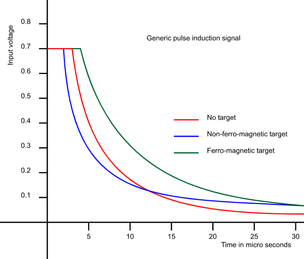
During the first five microseconds when the discharge curve is in stage 1 and stage 2, the signal is clamped by the protection diodes in the input circuit. After that the curve slowly decays, with the decay speed dependent on the existence of a target and the conductivity of that target. In the top of the curve, ferro-magnetic metals will cause a small delay of the signal to drop below 0.7 Volt, where non-ferrous metals will shift that transition point a little bit earlier. Highly conductive materials like gold, silver and copper will have a steep curve and decay rapidly to zero. We see that after about 30 microseconds, discrimination between different target types is almost impossible. By analyzing a number of these curves it is possible to make an educated guess about the material of a target detected by the pulse induction metal detector. As with all metal detectors it is an educated guess and not a definite answer, because size, depth, surrounding targets and soil response may alter the signal in such a way that proper discrimination is not possible.
Power supply design
One of the main problems when developing a good pulse induction metal detector with digital signal processing is a proper design of the power supply. The system will contain three power users which each their own specific needs. Peak currents in one part of the power supply should not have any negative effect on other parts in the system. Analog and digital ground should also be kept as separate as possible. This is not easy to achieve if we also want to source the whole circuit from one battery pack.
Coil supply
The coil is without doubt the largest current consumer in the circuit. Pulses which may reach several Amperes are generated by switching the coil on and off via a MOSFET. The coil should therefore directly be fed from the battery pack. No linear regulator or DC/DC converter will have the power to generate these short current pulses, without severe effects somewhere in the system. We can use a small series resistor and a large buffer capacitor to protect the batteries from large supply currents.
Analog amplification supply
The analog amplification stage works with a double power supply anywhere between ±5 and ±15 Volt. The center of these supplies should be connected to the fixed side of the coil and will be practically functioning as the analog ground in the circuit. The floating side will then be amplified relative to the supply center. Our design of the first stage of the amplifier will be fully differential which will reduce interference if the analog zero is not perfectly stable.
Digital signal processor supply
Digital signal processors are designed to work at 3.3 Volt, 5 Volt or both. I will use the higher supply voltage for two reasons. First of all has experience in the past learned that 5 Volt supplied processors have less problems with interference. But the main reason is that the DSP model I decided to use can only use the fastest ADC conversion mode when a 5 Volt power supply is connected. The position of the power supply in the total circuit is a difficult one. To switch the MOSFET that drives the coil, the zero supply line of the DSP should ideally be connected to the zero of the MOSFET which is at the outer end of the supplies. But for a proper sampling of the analog signals in the amplification stage, the zero the DSP should be around the zero of the amplification stage, which is in the center of the supplies. Because it is easier to shift the voltage levels of the analog stage with a differential amplifier than it is to switch the MOSFET from an arbitrary voltage level, we will connect the digital components to the negative supply line. This also automatically separates the analog and digital ground which reduces noise problems.
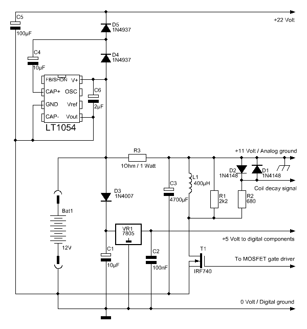
Schematics of the power part
After combining all wishes, the easiest to build power part of the circuit will be as in the next picture. The coil is powered almost directly from the battery pack. I say “almost directly” because a small resistor and large capacitor are used to reduce the peak currents. The digital components are placed close to the negative supply line. A linear power regulator, capacitors and a diode must prevent that too much of the noise generated by the digital parts is flowing back in the analog circuit. The op-amps in the analog amplifier need a double power source to operate. The upper part of this power supply is generated by the LT1054 chip in a voltage doubler configuration.
Effectively the connection point of the R3, C3 and the search coil is acting as the analog ground. This ground level will go up and down during the charge and de-charge stages of capacitor C3, but this will have no negative effect on the analog amplifier because the input circuitry of the amplification stage will be fully differential.
You can see that both the + and – terminal of the battery are defined as a star point. This should also be the case when designing the PCB. By having as short as possible common lines between the three main consumers (coil, processor and analog amplifier) the chance of interference between those components will get smaller.
|
Truth is what stands the test of experience.
ALBERT EINSTEIN
|