USB connector information
Introduction
The USB interface is one of the most used interfaces at this moment to connect peripheral equipment to computers. Although the USB interface itself is standard, and you should be able to connect every device to a USB enabled computer if the appropriate driver exists, problems may arise to find the right cable. This is because especially for smaller equipment like cameras different models of USB connectors have been defined. This document contains information about all known USB connector types and will help you to find the right cable to connect equipment to your computer.
Basic design concepts of USB connectors
Much effort has been put in the design of the several USB connectors to make them useful for their purpose. The old Centronics connectors for parallel printers were bulky and needed clips to connect them securely to the devices. The DB9 and DB25 connectors which are used for RS232 ports and parallel ports on computers often have problems with connection bolts falling out of the computer case if someone has accidentally tightened the screws of the connector to far. People who have often disconnected and reconnected their VGA cable might have experienced that these densely populated connectors have very thin pins which bend easily.
Another problem with bad connector design is that you may accidentally connect them wrong. This is something which can happen for example with flat cable connectors and power connectors inside computers. As USB can power devices over the cable it is not only necessary that an USB connector can not be connected in the wrong orientation, but the design must also not allow that two power providing USB devices are connected with each other as this may cause one or both power supplies to be damaged.
Standard A and B USB connectors
Because of all these reasons, two USB connectors have been defined for basic use, the USB A connector which must be used on devices which provide power (mostly computers), and the USB B connector used on devices which receive power like most peripheral devices.
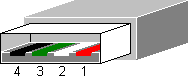
In the standard USB A and B connectors specified in the USB 1.1 and USB 2.0 specification, four pins are defined. Two pins are used for power and two pins are used for differential data transmission. If you look carefully at the connector you will see that the pins for the power connection (pin 1 and 4) are slightly longer. This is done on purpose to first connect the power supply when connecting a USB device, and only afterwards establish the data connection. With this sequence the chance that the driver or receiver ports of the data connection receive awkward and possible dangerous voltages is lowered substantially.
| Pin | Name | Color | Function |
|---|---|---|---|
| 1 | Vcc | Red | +5V supply voltage |
| 2 | D- | White | Data- signal line |
| 3 | D+ | Green | Data+ signal line |
| 4 | GND | Black | Supply ground |
Mini USB A and B connectors
The good thing of a USB connector standard is that it is possible to design devices without need to think how that device should be connected to other devices. The USB A and B connectors proofed their usability with devices like printers, modems and scanners, but when the faster USB 2.0 was released and USB became not only a way to connect slow and bulky equipment but also faster and smaller devices like photo camera’s and mobile telephones, especially the standard USB B connector was just too big to fit nicely on these smaller equipment. An update to the USB 2.0 specification was posted with the name Mini-B connector engineering change notice which defined a smaller version of the B connector. There has also existed a mini USB A connector for some time, but as the USB A connector is used on the power sourcing side—mostly a larger piece of equipment like a computer—that connector was withdrawn from the standard and no new devices will receive certification any more if they contain such a connector. In practice you won’t find the mini USB A connector any more.
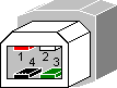
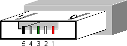
Besides the size, the main difference between the standard USB A and B connectors and the mini USB A and B versions is the extra pin which is called ID. In the mini connector series this pin is normally not connected. It has been added for future enhancements of the USB standard.
| Pin | Name | Color | Function |
|---|---|---|---|
| 1 | Vcc | Red | +5V supply voltage |
| 2 | D- | White | Data- signal line |
| 3 | D+ | Green | Data+ signal line |
| 4 | ID | – | not connected |
| 5 | GND | Black | Supply ground |
Micro USB AB and B connectors
In the modern world small is never small enough and the mini USB B connector soon was too large for new equipment like cell phones. Therefore in January 2007 the micro USB connector was announced which could be easier integrated in thin devices than the mini USB version. Although the micro USB connector is much thinner than its mini USB brother, it has been especially designed for rough use and the connector is specified for at least 10000 connect/disconnect cycles. One of the reasons is that with mobile devices like cell phones, PDAs and smartphones the number of mate cycles will be significantly higher than with static equipment like printers and mice. Furthermore the micro USB connector is becoming the de facto standard to charge mobile devices and its use will therefore be even more widespread than of its mini USB counterpart.
In the original USB specification there was a strict separation between the host (mostly a computer) which acts as a master device, and the peripherals which have only slave functionality. As mobile devices get smart and often run their own operating system, the separation between the two types of devices has vanished. When connected to a PC a smartphone may be acting as a slave, but it could also be connected to a photo printer directly to print pictures made with the phone. In that case the phone switches from its slave role to a master. To allow this an extension to the USB 2.0 specification has been written which is called USB On-The-Go or more often USB OTG. This supplement provides means for easy switching between the master and slave role of a device.
Because most small devices which can both act as a master and a slave only have one USB connector, additions to the connector definition were necessary to allow a role change with only one type of cable. This is where the mini USB AB and later the micro USB AB connector are defined for. The mini USB AB connector is now officially deprecated, but the micro USB AB connector is replacing its place rapidly. Countries like China are even considering to make this micro USB AB connector mandatory on all new cell phones sold. In this micro USB AB connector the ID pin is used to signal the master of slave function.
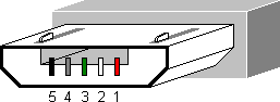
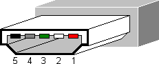
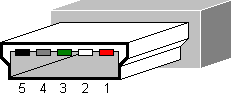
The pin numbering for the micro USB connectors is the same as for the mini USB connectors. The only difference is that for the micro USB AB connector the ID pin now has a function assigned to it.
| Pin | Name | Color | Function |
|---|---|---|---|
| 1 | VCC | Red | +5V supply voltage |
| 2 | D- | White | Data- signal line |
| 3 | D+ | Green | Data+ signal line |
| 4 | ID | – | not connected: works as B connector connected to GND: works as A connector |
| 5 | GND | Black | Supply ground |
|
Nothing ever gets built on schedule or within budget.
CHEOP'S LAW
|