Yost serial device wiring
- Introduction in the Yost wiring standard
- Goals of the Yost serial wiring standard
- The Yost cable
- Yost RS232 to RJ45 DTE adapter wiring
- Yost RS232 to RJ45 DCE adapter wiring
Introduction in the Yost wiring standard
The wiring of RS232 has always been a problem. Originally the standard was defined for DTE, data terminal equipment to DCE, data communication equipment connection, but soon people started to use the communication interface to connect two DTEs directly using null modem cables. No standard was defined for null modem connections with RS232 and not long after their introduction, several different wiring schemes became common. With DECConnect, Digital Equipment Corporation tried to define their own standard for serial interconnection of computer devices with MMJ modified modular jack connectors. This interfacing standard became available on most of their hardware, but it wasn’t adopted by other computer manufacturers. Maybe because DEC used an non-standard version of the modular jack.
UTP and FTP cables with RJ45 connectors became the de-facto standard in office cabling systems, and people started looking for ways to transmit RS232 signals over this cabling system. The RS-232D standard (more properly called EIA/TIA 561) was the official attempt for a standard to transmit RS232 over RJ45. Unfortunately this attempt didn’t twist the cable internally. Therefore it primarily remained a standard for DTE to DCE connection in a world where the primary use of RS232 was to interconnect DTEs directly.
Very interesting is the RS232 to RJ45 wiring standard proposed by Dave Yost in 1987, based on earlier wiring schemes used at Berkeley University. He tried to define a standard comparable to DECConnect, where both DTEs and DCEs could be connected with one cable type. This standard was published in the Unix System Administration Handbook in 1994, and has since that moment been a wiring standard for many organisations. We will discuss this standard in detail here.
Goals of the Yost device wiring standard
The mess with RS232 wiring is widely known. It was the reason for starting this website. Dave Yost wanted to solve that mess once and for all, reaching as much as possible of the following goals:
- All cable connectors should have the same connector type (RJ45)
- All cable connectors should have the same connector gender (male)
- DTEs and DCEs should have the same connector wiring
- All cables should be identical (except for length)
- No need for null modems or other special cables for specific situations
These goals are very close to the goals DEC wanted to achieve with DECConnect. The Yost standard has however one basic advantage. Because RJ45 connectors are used, eight pins are available which makes it possible to transfer almost all RS232 signals. Therefore the Yost standard can be used with much more equipment than DECConnect.
The Yost cable
One cable for all solutions is the basis of the Yost standard. This cable is not a straight through patch cable with two RJ45 connectors crimped to each end, but a cross-cable where pin 1 is connected to pin 8, pin 2 to 7 etc. The basic layout of this cable is shown below. In this picture flat cable is used, which is specially designed for use with RJ45 connectors. Do not use cross cables that are sold in some computer stores. Those cables cross some pairs to make the connection of two computers with Ethernet network cards possible without a hub, but these cables are not recommended for Yost systems.
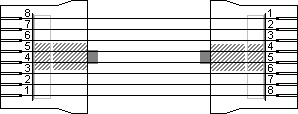
| RJ45 plug 1 | RJ45 plug 2 | Function |
|---|---|---|
| 1 | 8 | CTS ◄ RTS |
| 2 | 7 | CD ◄ DTR |
| 3 | 6 | Rx ◄ Tx |
| 4 | 5 | Signal ground |
| 5 | 4 | Signal ground |
| 6 | 3 | Tx ► Rx |
| 7 | 2 | DTR ► CD |
| 8 | 1 | RTS ► CTS |
I have used the DTE signal names here, just as is common with the DECConnect interface. DTE is the rule, DCE is the exception in that approach. The signal ground has been split in two lines to get a symmetric layout. Two common RS232 signals are missing on the RJ45 connector. The ring indicator RI is often not necessary because most modems also signal incoming rings with the text “RING” on the data lines. Data set ready DSR is not implemented because it can easily be emulated by connecting the DTR and DSR lines in the adapter at the DTE side.
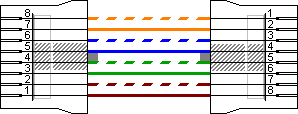
If twisted pair cable is used with the RJ45 connectors, the following pairs are advised to minimize cross-talk between the lines: 1-2, 3-4, 5-6 and 7-8. When twisting this way, both data lines are twisted with their own signal ground line, adding some noise immunity. Twisting of the handshake lines is less critical. The exact color-scheme to connect the twisted pair cable to the RJ45 connectors is not important for the functionality of the cable, but it is important for yourself to use only one color-scheme to prevent errors. If you don’t know which color-scheme to use, I advice the following which is a modified version of the EIA/TIA-568B color coding.
Yost DTE adapter wiring
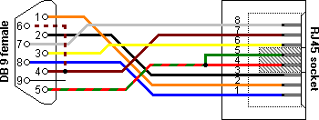
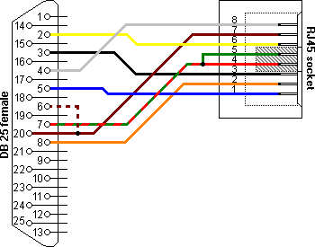
Now we know how the cables are wired, it is time to define the adapter wiring for various equipment. Depending of the type of equipment, DB9 or DB25 connectors are used. Layouts for both connectors to a RJ45 socket for DTE equipment is shown here. The colors are defined by the Yost standard. The DTR to DSR connection is optional. Please use the manual of the device or software to decide if this loop is necessary. It doesn’t harm most of the time if you connect both lines, even with systems that don’t use the DSR input signal.
| RJ45 | Function | Color | DB9 | DB25 |
|---|---|---|---|---|
| 1 | CTS | Blue | 8 | 5 |
| 2 | CD | Orange | 1 | 8 |
| 3 | Rx | Black | 2 | 3 |
| 4 | SG | Red | 5 | 7 |
| 5 | SG | Green | 5 | 7 |
| 6 | Tx | Yellow | 3 | 2 |
| 7 | DTR | Brown | 4 | 20 |
| 7 | DSR | (optional) | 6 | 6 |
| 8 | RTS | White | 7 | 4 |
A special note about printers
In the Yost standard, Dave Yost defines printers as DCE devices which is IMHO not correct. From an historical point of view, printers are just the predecessors of the terminal, with the teletype as intermediate. Also, the serial RS232 wiring diagrams I know for printers all use a modified null modem version for the connection to a computer, rather than a straight through connection which would be the case when the printer was wired as DCE.
But although the definition of printers as DCE might not be correct, the notes in the Yost standard about special precautions with the handshaking signals still apply. As there is no standard for wiring the handshaking signals of serial printers, my advice is to look at my serial printer page or—if available—in the technical manual of your device to find out which RS232 handshaking signals are used. Then wire the adapter accordingly.
Yost DCE adapter wiring
The wiring of a Yost RS232 to RJ45 adapter for a DCE is more or less a mirror of the DTE adapter wiring. The Yost standard defines the wiring scheme for both DB9 and DB25 connectors. Because DB9 connectors are rarely used on DCEs, there is only a picture of the larger version here. The table lists the pinouts for DB9 when needed in a specific situation.
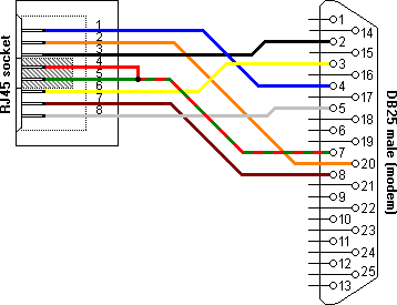
| RJ45 | Function | Color | DB9 | DB25 |
|---|---|---|---|---|
| 1 | RTS | Blue | 7 | 4 |
| 2 | DTR | Orange | 4 | 20 |
| 3 | Tx | Black | 3 | 2 |
| 4 | SG | Red | 5 | 7 |
| 5 | SG | Green | 5 | 7 |
| 6 | Rx | Yellow | 2 | 3 |
| 7 | CD | Brown | 1 | 8 |
| 8 | CTS | White | 8 | 5 |
|
Freedom is the right to tell people what they do not want to hear.
GEORGE ORWELL
|