RS485 serial information
- Introduction to RS485
- Differential signals with RS485
- Electrical characteristics of RS485
- Network topology with RS485
- RS485 functionality
Introduction to RS485
RS232, RS422, RS423 and RS485 are serial communication methods for computers and devices. RS232 is without doubt the best known interface, because this serial interface is implemented on almost all computers available today. But some of the other interfaces are certainly interesting because they can be used in situations where RS232 is not appropriate. We will concentrate on the RS485 interface here.
RS232 is an interface to connect one DTE, data terminal equipment to one DCE, data communication equipment at a maximum speed of 20 kbps with a maximum cable length of 50 feet. This was sufficient in the old days where almost all computer equipment were connected using modems, but soon after people started to look for interfaces capable of one or more of the following:
- Connect DTE’s directly without the need of modems
- Connect several DTE’s in a network structure
- Ability to communicate over longer distances
- Ability to communicate at faster communication rates
RS485 is the most versatile communication standard in the standard series defined by the EIA, as it performs well on all four points. That is why RS485 is currently a widely used communication interface in data acquisition and control applications where multiple nodes communicate with each other.
Differential signals with RS485:
Longer distances and higher bit rates
One of the main problems with RS232 is the lack of immunity for noise on the signal lines. The transmitter and receiver compare the voltages of the data- and handshake lines with one common zero line. Shifts in the ground level can have disastrous effects. Therefore the trigger level of the RS232 interface is set relatively high at ±3 Volt. Noise is easily picked up and limits both the maximum distance and communication speed. With RS485 on the contrary there is no such thing as a common zero as a signal reference. Several volts difference in the ground level of the RS485 transmitter and receiver does not cause any problems. The RS485 signals are floating and each signal is transmitted over a Sig+ line and a Sig- line. The RS485 receiver compares the voltage difference between both lines, instead of the absolute voltage level on a signal line. This works well and prevents the existence of ground loops, a common source of communication problems. The best results are achieved if the Sig+ and Sig- lines are twisted. The image below explains why.
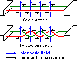
In the picture above, noise is generated by magnetic fields from the environment. The picture shows the magnetic field lines and the noise current in the RS485 data lines that is the result of that magnetic field. In the straight cable, all noise current is flowing in the same direction, practically generating a looping current just like in an ordinary transformer. When the cable is twisted, we see that in some parts of the signal lines the direction of the noise current is the oposite from the current in other parts of the cable. Because of this, the resulting noise current is many factors lower than with an ordinary straight cable. Shielding—which is a common method to prevent noise in RS232 lines—tries to keep hostile magnetic fields away from the signal lines. Twisted pairs in RS485 communication however adds immunity which is a much better way to fight noise. The magnetic fields are allowed to pass, but do no harm. If high noise immunity is needed, often a combination of twisting and shielding is used as for example in STP, shielded twisted pair and FTP, foiled twisted pair networking cables.
Differential signals and twisting allows RS485 to communicate over much longer communication distances than achievable with RS232. With RS485 communication distances of 1200 m are possible.
Differential signal lines also allow higher bit rates than possible with non-differential connections. Therefore RS485 can overcome the practical communication speed limit of RS232. Currently RS485 drivers are produced that can achieve a bit rate of 35 mbps.
Characteristics of RS485 compared to RS232, RS422 and RS423
| RS232 | RS423 | RS422 | RS485 | |
|---|---|---|---|---|
| Differential | no | no | yes | yes |
| Max number of drivers | 1 | 1 | 1 | 32 |
| Max number of receivers | 1 | 10 | 10 | 32 |
| Modes of operation | half duplex / full duplex | half duplex | half duplex | half duplex |
| Network topology | point-to-point | multidrop | multidrop | multipoint |
| Max distance (acc. standard) | 15m | 1200m | 1200m | 1200m |
| Max speed at 12m | 20kbps | 100kbps | 10Mbps | 35Mbps |
| Max speed at 1200m | (1kbps) | 1kbps | 100kbps | 100kbps |
| Max slew rate | 30V/μs | adjustable | n/a | n/a |
| Receiver input resistance | 3..7 kΩ | ≧ 4 kΩ | ≧ 4 kΩ | ≧ 12 kΩ |
| Driver load impedance | 3..7 kΩ | ≧ 450 Ω | 100 Ω | 54 Ω |
| Receiver input sensitivity | ±3 V | ±200 mV | ±200 mV | ±200 mV |
| Receiver input range | ±15 V | ±12 V | ±10 V | –7..12 V |
| Max driver output voltage | ±25 V | ±6 V | ±6 V | –7..12 V |
| Min driver output voltage (with load) | ±5 V | ±3.6 V | ±2.0 V | ±1.5 V |
What does all the information in this table tell us? First of all we see that the speed of the differential interfaces RS422 and RS485 is far superior to the single ended versions RS232 and RS423. We also see that there is a maximum slew rate defined for both RS232 and RS423. This has been done to avoid reflections of signals. The maximum slew rate also limits the maximum communication speed on the line. For both other interfaces—RS422 and RS485—the slew rate is indefinite. To avoid reflections on longer cables it is necessary to use appropriate termination resitors.
We also see that the maximum allowed voltage levels for all interfaces are in the same range, but that the signal level is lower for the faster interfaces. Because of this RS485 and the others can be used in situations with a severe ground level shift of several volts, where at the same time high bit rates are possible because the transition between logical 0 and logical 1 is only a few hundred millivolts.
Interesting is, that RS232 is the only interface capable of full duplex communication. This is, because on the other interfaces the communication channel is shared by multiple receivers and—in the case of RS485—by multiple senders. RS232 has a separate communication line for transmitting and receiving which—with a well written protocol—allows higher effective data rates at the same bit rate than the other interfaces. The request and acknowledge data needed in most protocols does not consume bandwidth on the primary data channel of RS232.
Network topology with RS485
Network topology is probably the reason why RS485 is now the favorite of the four mentioned interfaces in data acquisition and control applications. RS485 is the only of the interfaces capable of internetworking multiple transmitters and receivers in the same network. When using the default RS485 receivers with an input resistance of 12 kΩ it is possible to connect 32 devices to the network. Currently available high-resistance RS485 inputs allow this number to be expanded to 256. RS485 repeaters are also available which make it possible to increase the number of nodes to several thousands, spanning multiple kilometers. And that with an interface which does not require intelligent network hardware: the implementation on the software side is not much more difficult than with RS232. It is the reason why RS485 is so popular with computers, PLCs, micro controllers and intelligent sensors in scientific and technical applications.
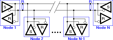
In the picture above, the general network topology of RS485 is shown. N nodes are connected in a multipoint RS485 network. For higher speeds and longer lines, the termination resistances are necessary on both ends of the line to eliminate reflections. Use 100 Ω resistors on both ends. The RS485 network must be designed as one line with multiple drops, not as a star. Although total cable length maybe shorter in a star configuration, adequate termination is not possible anymore and signal quality may degrade significantly.
RS485 functionality
And now the most important question, how does RS485 function in practice? Default, all the senders on the RS485 bus are in tri-state with high impedance. In most higher level protocols, one of the nodes is defined as a master which sends queries or commands over the RS485 bus. All other nodes receive these data. Depending of the information in the sent data, zero or more nodes on the line respond to the master. In this situation, bandwidth can be used for almost 100%. There are other implementations of RS485 networks where every node can start a data session on its own. This is comparable with the way ethernet networks function. Because there is a chance of data collosion with this implementation, theory tells us that in this case only 37% of the bandwidth will be effectively used. With such an implementation of a RS485 network it is necessary that there is error detection implemented in the higher level protocol to detect the data corruption and resend the information at a later time.
There is no need for the senders to explicity turn the RS485 driver on or off. RS485 drivers automatically return to their high impedance tri-state within a few microseconds after the data has been sent. Therefore it is not needed to have delays between the data packets on the RS485 bus.
RS485 is used as the electrical layer for many well known interface standards, including Profibus and Modbus. Therefore RS485 will be in use for many years in the future.
|
The more studying you did for the exam,
the less sure you are as to which answer they want.
SECOND LAW OF APPLIED TERROR
|